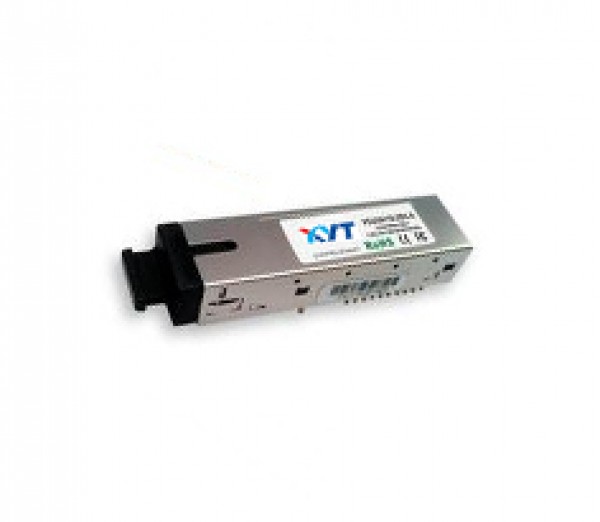
- Specification -
Table 1-Optical and Electrical Characteristics
Parameter | Symbol | Min | Typical | Max | Unit | Notes |
Transmitter |
Data Rate | | | 1.25 | | Gb/S | |
Centre Wavelength | λc | 1480 | | 1500 | nm | |
Spectral Width | ?λ | | 0.4 | 1 | nm | |
Side Mode Suppression Ratio | SMSR | 30 | | | dB | |
Average Output Power(BOL) | Pout | 3 | | 7 | dBm | 1 |
Average Output Power(EOL) | Pout | 2 | | 7 | dBm | 1 |
Extinction Ratio | ER | 9 | | | dB | |
Average Launch Power-OFF Transmitter | Poff | | | -40 | dBm | |
Optical Eye Diagram | Compliant with IEEE802.3ah-2004 PX20 |
Optical Rise/Fall Time(20%~80%) | tr/tf | | | 260 | ps | |
Data Input Swing Differential | VIN | 200 | | 2400 | mV | 2 |
Input Differential Impedance | ZIN | 90 | 100 | 110 | Ω | |
TX Disable | Disable | | 2 | | Vcc | V | |
Enable | | 0 | | 0.8 | V | |
TX Fault | Fault | | 2 | | Vcc | V | |
Normal | | 0 | | 0.8 | V | |
Receiver |
Data Rate | | | 1.25 | | Gb/S | |
Centre Wavelength | λc | 1260 | | 1360 | nm | |
Receiver Sensitivity | Sen | | | -28 | dBm | 3 |
Receiver Overload | Sat | -6 | | | dBm | 3 |
Receiver Burst Dynamic Range | | 22 | | | dB | |
Receiver Reflectance | | | | -20 | dB | |
Data Output Voltage-High | VOH | VccR-1.05 | | VccR – 0.85 | V | 4 |
Data Output Voltage-Low | VOL | VccR-1.84 | | VccR – 1.60 | V | 4 |
LOS De-assert Level | LOS_D | | | -29 | dBm | |
LOS Assert Level | LOS_A | -45 | | | dBm | |
LOS Detect Hysteresis | | 1 | | | dBm | |
LOS_Det High | | 2 | | VCC | V | |
LOS_Det Low | | 0 | | 0.8 | V | |
LOS De-assert Time | LOS_D T | | | 500 | ns | |
LOS Assert Time | LOS_A T | | | 500 | ns | |
Reciever Power DDM(RSSI)Error | RXDDM | | | +/-3 | dBm | |
Notes:
Plug Seq.:Pin engagement sequence during hot plugging.
1)TX Fault is an open collector output,which should be pulled up with a 4.7k~10kΩ resistor on the host board to a voltage between 2.0V and Vcc+0.3V.Logic 0 indicates normal operation;Logic 1 indicates a laser fault of some kind.In the low state,the output will be pulled to less than 0.8V.
2)TX Disable is an input that is used to shut down the transmitter optical output.It is pulled up within the module with a 4.7k~10kΩ resistor.Its states are:
Low(0 to 0.8V): Transmitter on
(>0.8V,<2.0V): Undefined
High(2.0 to 3.465V): Transmitter Disable
Open: Transmitter Disabled
3)Mod-Def 0,1,2.These are the module definition pins.They should be pulled up with a 4.7k~10kΩ resistor on the host board.The pull-up voltage shall be VccT or VccR.
Mod-Def 0 is grounded by the module to indicate that the module is present
Mod-Def 1 is the clock line of two wire serial interface for serial ID
Mod-Def 2 is the data line of two wire serial interface for serial ID
4)LOS(Loss of Signal)is an open collector/drain output,which should be pulled up with a 4.7K – 10KΩ resistor.Pull up voltage between 2.0V and VccT,R+0.3V.When high,this output indicates the received optical power is below the worst-case receiver sensitivity(as defined by the standard in use).Low indicates normal operation.In the low state,the output will be pulled to<0.8V.
5)RD-/+:These are the differential receiver outputs.They are internally DC-coupled 100 differential lines which should be terminated with 100Ω(differential)at the user SERDES.
6)TD-/+:These are the differential transmitter inputs.They are internally AC-coupled,differential lines with 100Ω differential termination inside the module.
Table 2-Product selection
Wavelength | xx or yy | Clasp Color Code | Wavelength | xx or yy | Clasp Color Code |
1270 nm | 27 | Gray | 1450 nm | 45 | Brown |
1290 nm | 29 | Gray | 1470 nm | 47 | Gray |
1310 nm | 31 | Gray | 1490 nm | 49 | Purple |
1330nm | 33 | Purple | 1510 nm | 51 | Blue |
1350 nm | 35 | Blue | 1530 nm | 53 | Green |
1370 nm | 37 | Green | 1550 nm | 55 | Yellow |
1390 nm | 39 | Yellow | 1570 nm | 57 | Orange |
1410 nm | 41 | Orange | 1590 nm | 59 | Red |
1430 nm | 43 | Red | 1610 nm | 61 | Brown |
Ordering information
Product part | Data Rate | Wavelength(nm) | Temperature |
Number | (Mbps) | Tx(Rx) | Range(℃)(Tcase) |
XTY-U3432-20DA-1 | 1244Mbps Upstream/ | 1490(1310) | 0~70 |
2488Mbps Downstream |
XTY-U3432-20DA-2 | 1244Mbps Upstream/ | 1490(1310) | -40~85 |

 Français