Français



Transceiver Block Diagrams
ModSelL:
The ModSelL is an input pin. When held low by the host, the module responds to 2-wire serial communication commands. The ModSelL allows the use of multiple modules on a single 2-wire interface bus. When the Mod-SelL is"High", the module shall not respond to or acknowledge any 2-wire interface communication from the host. ModSelL signal input node shall be biased to the"High"state in the module. In order to avoid conflicts, the host system shall not attempt 2-wire interface communications within the Mod-SelL de-assert time after any modules are deselected. Similarly, the host shall wait at least for the period of the ModSelL assert time before communicating with the newly selected module. The assertion and de-asserting periods of different modules may overlap as long as the above timing requirements are met.
ResetL :
The ResetL pin shall be pulled to Vcc in the module. A low level on the ResetL pin for longer than the mini-mum pulse length (t_Reset_init) initiates a complete module reset, returning all user module settings to their default state. Module Reset Assert Time (t_init) starts on the rising edge after the low level on the ResetL pin is released. During the execution of a reset (t_init) the host shall disregard all status bits until the module indi-cates a completion of the reset interrupt. The module indicates this by asserting"low"an IntL signal with the Data_Not_Ready bit negated. Note that on power up (including hot insertion) the module should post this completion of reset interrupt without requiring a reset.
LPMode:
The LPMode pin shall be pulled up to Vcc in the module. The pin is a hardware control used to put modules into a low power mode when high. By using the LPMode pin and a combination of the Power override, Power_set and High_Power_Class_Enable software control bits (Address A0h, byte 93 bits 0,1,2).
ModPrsL:
ModPrsL is pulled up to Vcc_Host on the host board and grounded in the module. The ModPrsL is asserted"Low"when inserted and deasserted"High"when the module is physically absent from the host connector.
IntL:
IntL is an output pin. When IntL is"Low", it indicates a possible module operational fault or a status critical to the host system. The host identifies the source of the interrupt using the 2-wire serial interface. The IntL pin is an open collector output and shall be pulled to host supply voltage on the host board. The INTL pin is deas-serted"High"after completion of reset, when byte 2 bit 0 (Data Not Ready) is read with a value of '0' and the flag field is read .
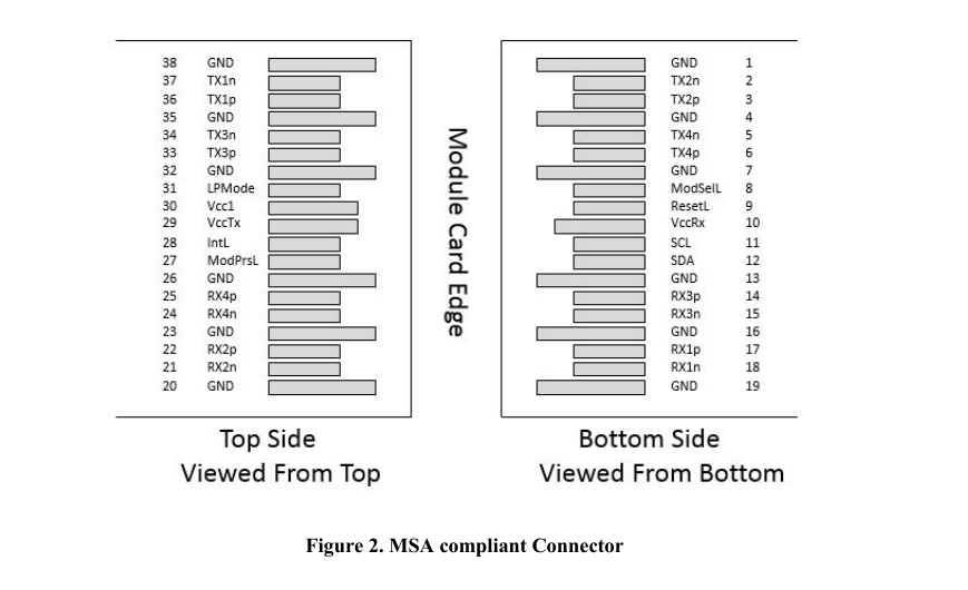
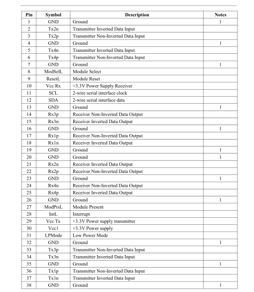
Pin Descriptions
Notes
1.Circuit ground is internally isolated from chassis ground.
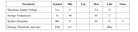
Absolute Maximum Ratings
It has to be noted that the operation in excess of any individual absolute maximum ratings might cause perma-nent damage to this module.
Notes
1. Non-condensing
Operating Environments
Electricalandopticalcharacteristicsbelowaredefinedunderthisoperatingenvironment,unlessotherwisespec-ified.
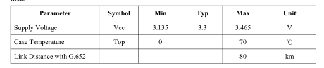
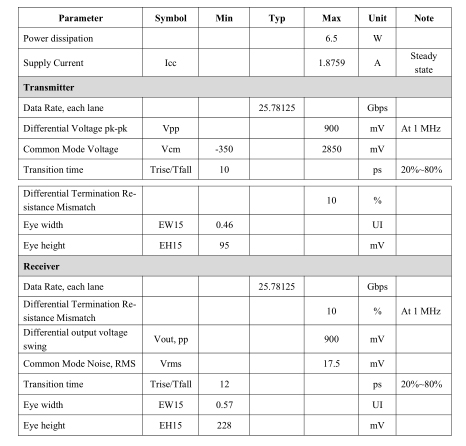
Electrical Characteristics
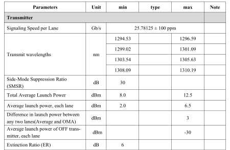
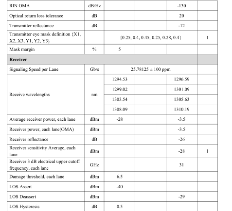
Optical Characteristics
100GBASE-ZR4 Operation(EOL, TOP = 0 to +70 ℃ , VCC = 3.135 to 3.465 Volts)
Notes
1,Sensitivity is specified at BER@5E-5 with FEC
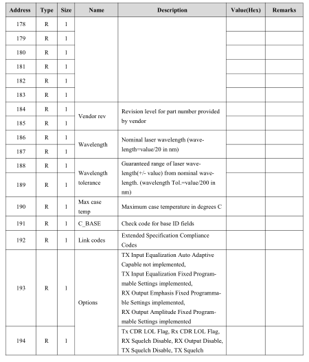
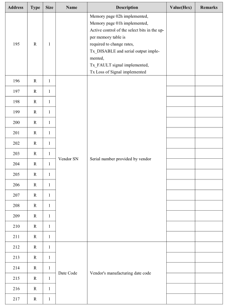
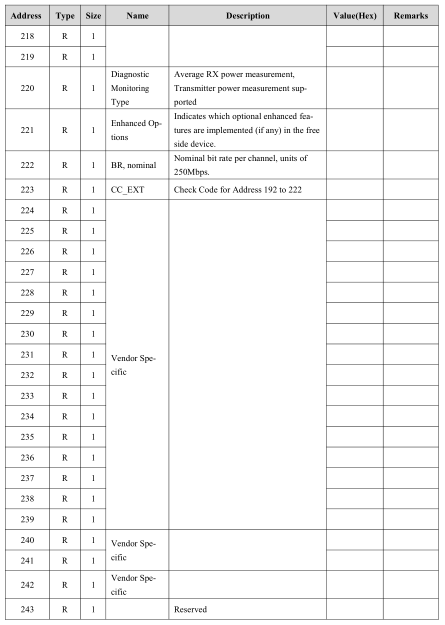
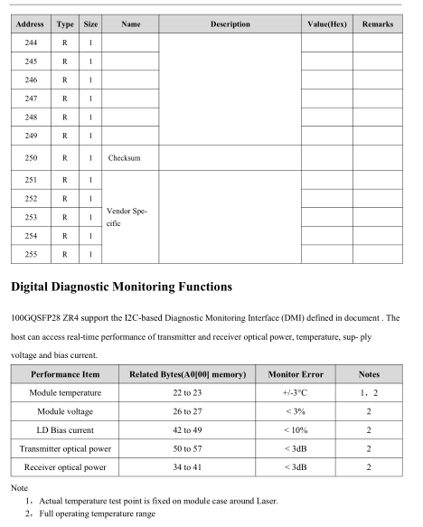
EEPROM Definitions
Lower Memory Map
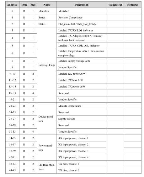
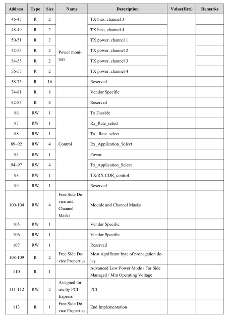
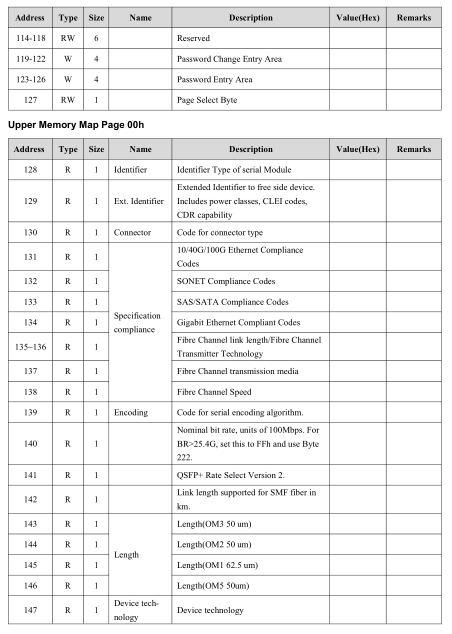
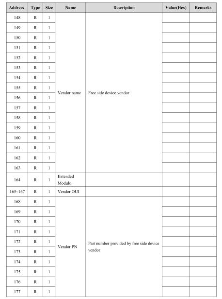
ModSelL:
The ModSelL is an input pin. When held low by the host, the module responds to 2-wire serial communication commands. The ModSelL allows the use of multiple modules on a single 2-wire interface bus. When the Mod-SelL is"High", the module shall not respond to or acknowledge any 2-wire interface communication from the host. ModSelL signal input node shall be biased to the"High"state in the module. In order to avoid conflicts, the host system shall not attempt 2-wire interface communications within the Mod-SelL de-assert time after any modules are deselected. Similarly, the host shall wait at least for the period of the ModSelL assert time before communicating with the newly selected module. The assertion and de-asserting periods of different modules may overlap as long as the above timing requirements are met.
ResetL :
The ResetL pin shall be pulled to Vcc in the module. A low level on the ResetL pin for longer than the mini-mum pulse length (t_Reset_init) initiates a complete module reset, returning all user module settings to their default state. Module Reset Assert Time (t_init) starts on the rising edge after the low level on the ResetL pin is released. During the execution of a reset (t_init) the host shall disregard all status bits until the module indi-cates a completion of the reset interrupt. The module indicates this by asserting"low"an IntL signal with the Data_Not_Ready bit negated. Note that on power up (including hot insertion) the module should post this completion of reset interrupt without requiring a reset.
LPMode:
The LPMode pin shall be pulled up to Vcc in the module. The pin is a hardware control used to put modules into a low power mode when high. By using the LPMode pin and a combination of the Power override, Power_set and High_Power_Class_Enable software control bits (Address A0h, byte 93 bits 0,1,2).
ModPrsL:
ModPrsL is pulled up to Vcc_Host on the host board and grounded in the module. The ModPrsL is asserted"Low"when inserted and deasserted"High"when the module is physically absent from the host connector.
IntL:
IntL is an output pin. When IntL is"Low", it indicates a possible module operational fault or a status critical to the host system. The host identifies the source of the interrupt using the 2-wire serial interface. The IntL pin is an open collector output and shall be pulled to host supply voltage on the host board. The INTL pin is deas-serted"High"after completion of reset, when byte 2 bit 0 (Data Not Ready) is read with a value of '0' and the flag field is read .
Pin Descriptions
Notes
1.Circuit ground is internally isolated from chassis ground.
Absolute Maximum Ratings
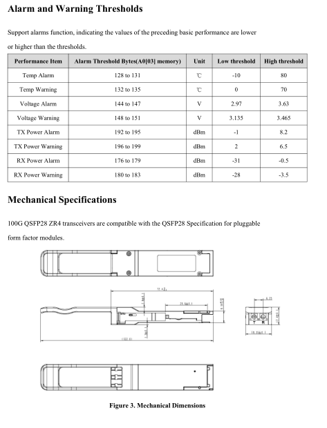
It has to be noted that the operation in excess of any individual absolute maximum ratings might cause perma-nent damage to this module.
Notes
1. Non-condensing
Operating Environments
Electricalandopticalcharacteristicsbelowaredefinedunderthisoperatingenvironment,unlessotherwisespec-ified.
Electrical Characteristics
Optical Characteristics
100GBASE-ZR4 Operation(EOL, TOP = 0 to +70 ℃ , VCC = 3.135 to 3.465 Volts)
Notes
1,Sensitivity is specified at BER@5E-5 with FEC
EEPROM Definitions
Lower Memory Map
Send Message
Related Products

Model NO. XYT-SFP+SR

Model NO. XYT-10G-SFP+

Model NO. XYT-SFP+LR

Model NO. XYT-SFP+ER-1310

Model NO. XYT-SFP+ZR

Model NO. XYT-SFP+BD-T1330/R1270-60

Model NO. XYT-SFP+BD-T1270/R1330-10

Model NO. XYT-SFP+BD-T1270/R1330-40